
بازدیدکننده گرامی این صفحه در حال بروزرسانی و بازطراحی میباشد لذا ممکن است در حال حاضر برخی از مطالب قابل رویت نباشند

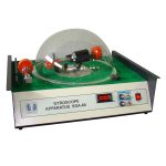
  • Equipped with a precision RPM sensor and a digital display for instantaneous angular velocity, and includes switches for reversing rotor direction and controlling the gimbal drive
  • Rotor fitted with a suitable motor and driver capable of increasing the rotor speed up to 3500 RPM
  • Includes an adjustment bolt for increasing and decreasing the angular velocity of both the gimbal driver and the rotor
  • Closed-loop control of rotor speed and RPM
  • Features a low-friction gimbal joint, and a rotor-balancing mechanism for proper alignment before applying counterbalance weights
  • Equipped with a bifilar suspension system to determine the actual moment of inertia of the inertia of motor rotor and its components
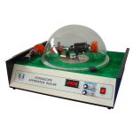
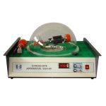
  • Supplied with a transparent, impact-resistant protective cover for safe monitoring of operation
  • Includes a counterbalance component to compensate for the rotor weight before installing the test mass
  • Safe and easy to operate

This machine is used to determine the gyroscopic couple value and couple to evaluate the rotary dynamics of a gyroscope under different rotor moments of inertia, angular velocities. For ease of operation, the apparatus includes buttons and switches for adjusting the angular velocity and controlling the rotation direction.

Moment of inertia is determined using bifilar suspension method. For doing so, fasten the rotor winding and its components (identical to those used in the apparatus rotor) to the hanger using two ropes and two bolts. Manually displace the bifilar setup by small angle around the axis between two hangers, then release it and allow it to oscillate freely. The oscillation period (typically measured over 50 cycles) is obtained by recording the total time of the full set of oscillations. Finally, substitute the measured parameters and geometric dimensions into the moment-of-inertia formula to calculate the value.

When measuring the gyroscope couple, first adjust the counterbalance mass along the arm until the arm is in a see-saw equilibrium. For the test, screw the required test weights onto the weight holder. Then, increase the gimbal and rotor speeds until the generated gyroscopic couple lifts the test weight and the system reaches a balanced see-saw position. Using the recorded data, the linearity of the governing relationships can be evaluated by plotting the corresponding graphs. Typically, the graphs are plotted for gyroscopic couple versus rotor speed, gyroscopic couple versus gimbal speed, and gyroscopic couple versus rotor-gimbal speed.

To ensure operational safety, the apparatus is equipped with a transparent protective cover and a limit switch that automatically stops operation if the protective cover is not properly installed.

This apparatus is designed to investigate the gyroscopic couples generated under various operating conditions and to compare the experimental results with theoretical predictions. Using the recorded data, the effects of rotation direction, gimbal drive speed, rotor angular velocity, and moment of inertia on the gyroscopic couple can be analyzed.​

Reviews

There are no reviews yet.

Be the first to review “Gyroscope Apparatus – SBA-60”
To inquire about the product price, copy its code

قبل از ادامه دادن، مطمئن شوید که نام محصول را کپی کرده‌اید

برای دسترسی به این فرم لازم است به حساب کاربری خود در سایت سنتام وارد شوید

سازنده:

شرکت طراحی مهندسی سنتام

استعلام قیمت

درخواست مشاوره

دانلود کاتالوگ

شرایط تحویل حضوری

شرایط تحویل کالا در محل کارخانه

جزییات بیشتر

شرایط ارسال دستگاه

شرایط ارسال دستگاه و حمل آن

جزییات بیشتر

متن آزمایشی

متن آزمایشی

جزییات بیشتر

گارانتی دستگاه

شرایط خدمات پس از فروش

جزییات بیشتر

جزییات بیشتر

  • Equipped with a precision RPM sensor and a digital display for instantaneous angular velocity, and includes switches for reversing rotor direction and controlling the gimbal drive
  • Rotor fitted with a suitable motor and driver capable of increasing the rotor speed up to 3500 RPM
  • Includes an adjustment bolt for increasing and decreasing the angular velocity of both the gimbal driver and the rotor
  • Closed-loop control of rotor speed and RPM
  • Features a low-friction gimbal joint, and a rotor-balancing mechanism for proper alignment before applying counterbalance weights
  • Equipped with a bifilar suspension system to determine the actual moment of inertia of the inertia of motor rotor and its components
  • Supplied with a transparent, impact-resistant protective cover for safe monitoring of operation
  • Includes a counterbalance component to compensate for the rotor weight before installing the test mass
  • Safe and easy to operate
This machine is used to determine the gyroscopic couple value and couple to evaluate the rotary dynamics of a gyroscope under different rotor moments of inertia, angular velocities. For ease of operation, the apparatus includes buttons and switches for adjusting the angular velocity and controlling the rotation direction. Moment of inertia is determined using bifilar suspension method. For doing so, fasten the rotor winding and its components (identical to those used in the apparatus rotor) to the hanger using two ropes and two bolts. Manually displace the bifilar setup by small angle around the axis between two hangers, then release it and allow it to oscillate freely. The oscillation period (typically measured over 50 cycles) is obtained by recording the total time of the full set of oscillations. Finally, substitute the measured parameters and geometric dimensions into the moment-of-inertia formula to calculate the value. When measuring the gyroscope couple, first adjust the counterbalance mass along the arm until the arm is in a see-saw equilibrium. For the test, screw the required test weights onto the weight holder. Then, increase the gimbal and rotor speeds until the generated gyroscopic couple lifts the test weight and the system reaches a balanced see-saw position. Using the recorded data, the linearity of the governing relationships can be evaluated by plotting the corresponding graphs. Typically, the graphs are plotted for gyroscopic couple versus rotor speed, gyroscopic couple versus gimbal speed, and gyroscopic couple versus rotor-gimbal speed. To ensure operational safety, the apparatus is equipped with a transparent protective cover and a limit switch that automatically stops operation if the protective cover is not properly installed.

این بخش در حال بروز رسانی می باشد...

[ywtm_content]

این بخش در حال بروز رسانی می باشد...